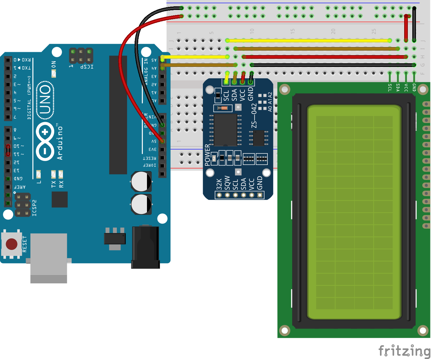

Putting a buffer gate between the clock output of the tiny USI and the SCL line of the I2C bus, so that one GPIO pin on the tiny can control it.
#BOTH I2C AND SPI ARDUINO SOFTWARE#
Software implementation of I2C on two spare GPIO pins. But when it's in SPI mode to talk to the radio module, surely the data and clock lines will be such that the I2C device thinks a transaction is ongoing? Anything I can do to prevent this? But how might this interact with external hardware? When it's in I2C mode to talk to the other device, the SPI device's SS line is deasserted, so the SPI radio will just ignore it. I know the USI itself has mode bits to switch it from three- to two-wire mode, so I could have it talk SPI or I2C. Arduino libraries for both I2C and SPI make it easy for you to use both of these protocols.

I know the USI can talk I2C as well, but I'm already using it to talk SPI to the radio. The I2C (Inter-Integrated Circuit) and SPI (Serial Peripheral Interface) standards were created to provide simple ways for digital information to be transferred between sensors and microcontrollers such as Arduino. Additionally, I have five digital temperature sensors using the IC bus in a timer interrupt routine executed every second. My next sensor project involves a sensor with an I2C interface. I have a couple of A/D converters and am reading them every 100 s over SPI, using the timer interrupt routine with SPI clocked at 16 MHz. I2C protocol can support multiple slave devices but unlike SPI, which only supports one master. This is good for hacking up sensors and whatnot as little radio devices. These two wires are SDA (Serial Data) and SCL (Serial Clock). I've been successfully using the USI on an Attiny84 to talk SPI to a radio module.


 0 kommentar(er)
